Beam Deflection & Stress Calculator (with Diagrams)
Deflection, reactions, bending moment and stress for supported and cantilever beams · free, no signup
Diagrams
See Beam Deflection & Stress Calculator (with Diagrams) in action
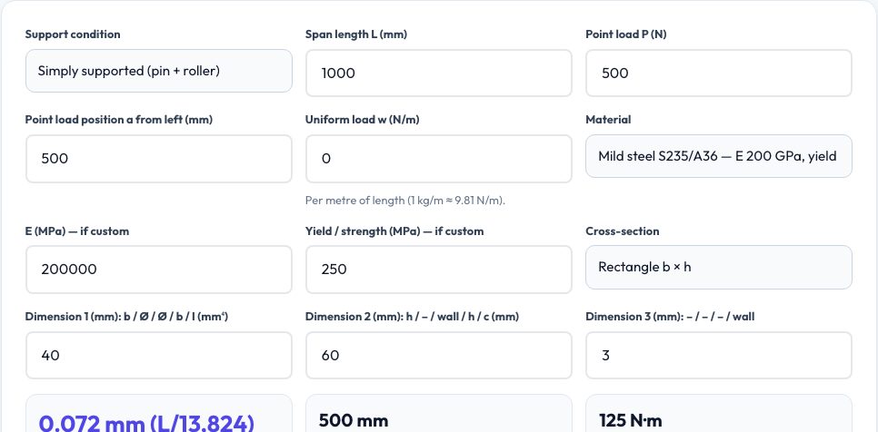
Free Beam Deflection & Bending Stress Calculator
Choose the support condition — simply supported, cantilever or fixed at both ends — enter the span, a point load and its position, an optional uniform load, a material and a cross-section, and the calculator returns the maximum deflection (and the L/deflection ratio), where it occurs, the support reactions, the maximum bending moment, the maximum bending stress and the safety factor against yield. Shear force, bending moment and deflection are drawn as diagrams along the beam.
The results come from the standard Euler–Bernoulli beam equations, with the point and distributed loads superposed (verified against closed-form textbook cases such as 5wL⁴/384EI and PL³/48EI). Materials include steel, stainless, aluminium, titanium, copper, printed PLA/PETG/ABS and softwood with typical modulus and strength; sections include rectangle, round bar, round tube and rectangular tube, or enter I and c directly.
Key features
Three support cases
Simply supported, cantilever and fixed-fixed with point + uniform loads.
Complete results
Deflection, reactions, moments, stress and safety factor.
Diagrams
Shear, moment and deflection plotted along the span.
Material library
Metals, printed plastics and wood with typical E and strength.
How to use it
- Pick support type, length and loads.
- Choose material and cross-section dimensions.
- Read deflection, moment, stress and safety factor.
- Check the diagrams and the L/360 guideline.
Worked example
Example
A 1 m simply supported 40×60 mm steel bar with a 500 N central load: deflection 0.072 mm (L/13,800), maximum moment 125 N·m, bending stress 5.2 MPa, safety factor 48 against 250 MPa yield.
Who uses this tool
Engineering students
Check statics and strength-of-materials homework.
Makers designing shelves and frames
See whether a 3D-printed or wooden beam is stiff enough.
Designers
Pre-size members before FEA.
Tips for the best results
- Check deflection as well as stress — stiffness often governs.
- Printed plastics are anisotropic; use the weakest direction's strength.
- Add a safety factor of at least 2 for static loads, more for dynamic.
- Remember this is elastic beam theory, not buckling or connection design.
Common mistakes to avoid
- Mixing units — loads are N, lengths mm, uniform load N/m.
- Using yield strength of the bulk material for printed parts.
- Ignoring self-weight on long spans.
Why use AZRS QuickFix?
It is 100% free, needs no signup and has no watermark or usage limits. The tool runs in your browser, so what you type stays on your device, and it works on phones, tablets and desktops. New tools are added every week — bookmark this page or browse the full QuickFix toolbox.
Frequently asked questions
Which beam theory is used?
Linear Euler–Bernoulli beam theory with small deflections.
Does it include shear deformation?
No — fine for slender beams (L/h > 10).
Can I combine loads?
Yes — one point load plus one uniform load are superposed.
What about multiple point loads?
Run separate cases and add the results (superposition).